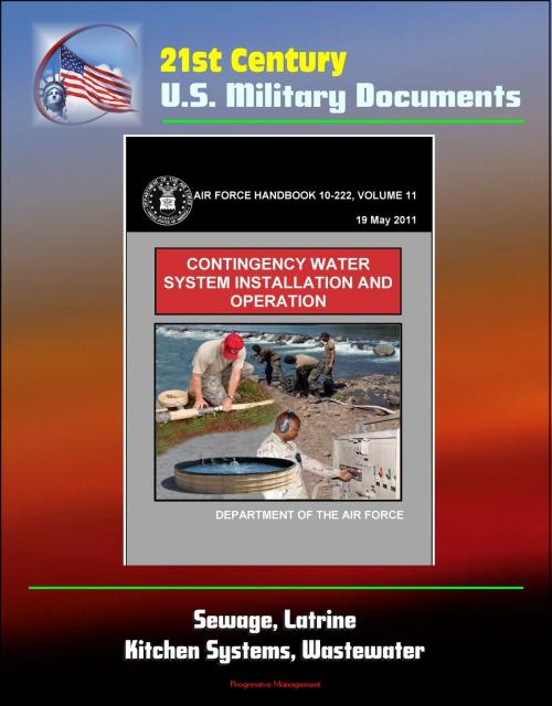
21st Century U.S. Military Documents: Contingency Water System Installation and Operation (Air Force Handbook 10-222) - Sewage, Latrine, Kitchen Systems, Wastewater
Nonfiction, Science & Nature, Technology, Engineering, Environmental| Author: | Progressive Management | ISBN: | 9781301402595 |
| Publisher: | Progressive Management | Publication: | October 8, 2013 |
| Imprint: | Smashwords Edition | Language: | English |
| Author: | Progressive Management |
| ISBN: | 9781301402595 |
| Publisher: | Progressive Management |
| Publication: | October 8, 2013 |
| Imprint: | Smashwords Edition |
| Language: | English |
This handbook provides USAF civil engineers with guidance on the installation and use of Air Force contingency water systems. It addresses site location and layout, assembly, and operation of water system components at bare base or austere locations. This handbook addresses general characteristics, setup, and basic operating procedures for the contingency water system and targets civil engineer utilities personnel while performing their beddown and sustainment mission taskings under contingency conditions. The contingency water system fulfills potable water and wastewater recovery needs at austere locations. The water system provides water to support kitchens, latrines, showers, laundries, and other bare base facilities and recovers the wastewater for appropriate disposal. The system is semi-automatic in that the 3,000-gallon facility storage tanks will fill automatically as long as the manually filled 20,000-gallon storage tanks are kept at the appropriate level. Once the system has been filled to capacity, water should be available for 5 days given 30 gallons per person per day usage. The removal of facility wastewater is also automatic under normal circumstances and does not require manual intervention.
Chapter 1 * INTRODUCTION * 1.1. Scope * 1.2. Overview * 1.3. General Information * 1.4. Water System Design and Capacity * 1.5. Safety * 1.6. Additional Information * Chapter 2 * PLANNING AND PREPARATION * 2.1. General Information * 2.2. Site Selection * 2.3. Layout * 2.4. Equipment Preparation * 2.5. System Flexibility * 2.6. Subsystems Interface * Chapter 3 * SOURCE RUN SUBSYSTEM * 3.1. General Information * 3.2. Components * 3.3. Installation * 3.4. Operation * 3.5. Component Descriptions * Chapter 4 * WATER PRODUCTION SUBSYSTEM * 4.1. General Information * 4.2. Components * 4.3. Installation * 4.4. Operation * 4.5. WPS Component Descriptions * Chapter 5 * 550-INITIAL SUBSYSTEM * 5.1. General Information * 5.2. Components * 5.3. Installation * 5.4. Operation * 5.5. Component Descriptions * Chapter 6 * 550-FOLLOW-ON SUBSYSTEM * 6.1. General Information * 6.2. Components * 6.3. Installation * 6.4. Operation * 6.5. Component Descriptions * Chapter 7 * INDUSTRIAL OPERATIONS AND FLIGHTLINE EXTENSION SUBSYSTEM * 7.1. General Information * 7.2. Components * 7.3. Installation * 7.4. Operation * 7.5. Component Descriptions * Attachment 1 * GLOSSARY OF REFERENCES AND SUPPORTING INFORMATION * Attachment 2 * COMPONENTS ILLUSTRATIONS * Attachment 3 * HOSE QUICK- DISCONNECT (QD) COUPLING CONNECTIONS * Attachment 4 * HOSE BRIDGE SYSTEM ASSEMBLY * Attachment 5 * NORMAL OPERATION OF THE CONTINGENCY WATER SYSTEM
